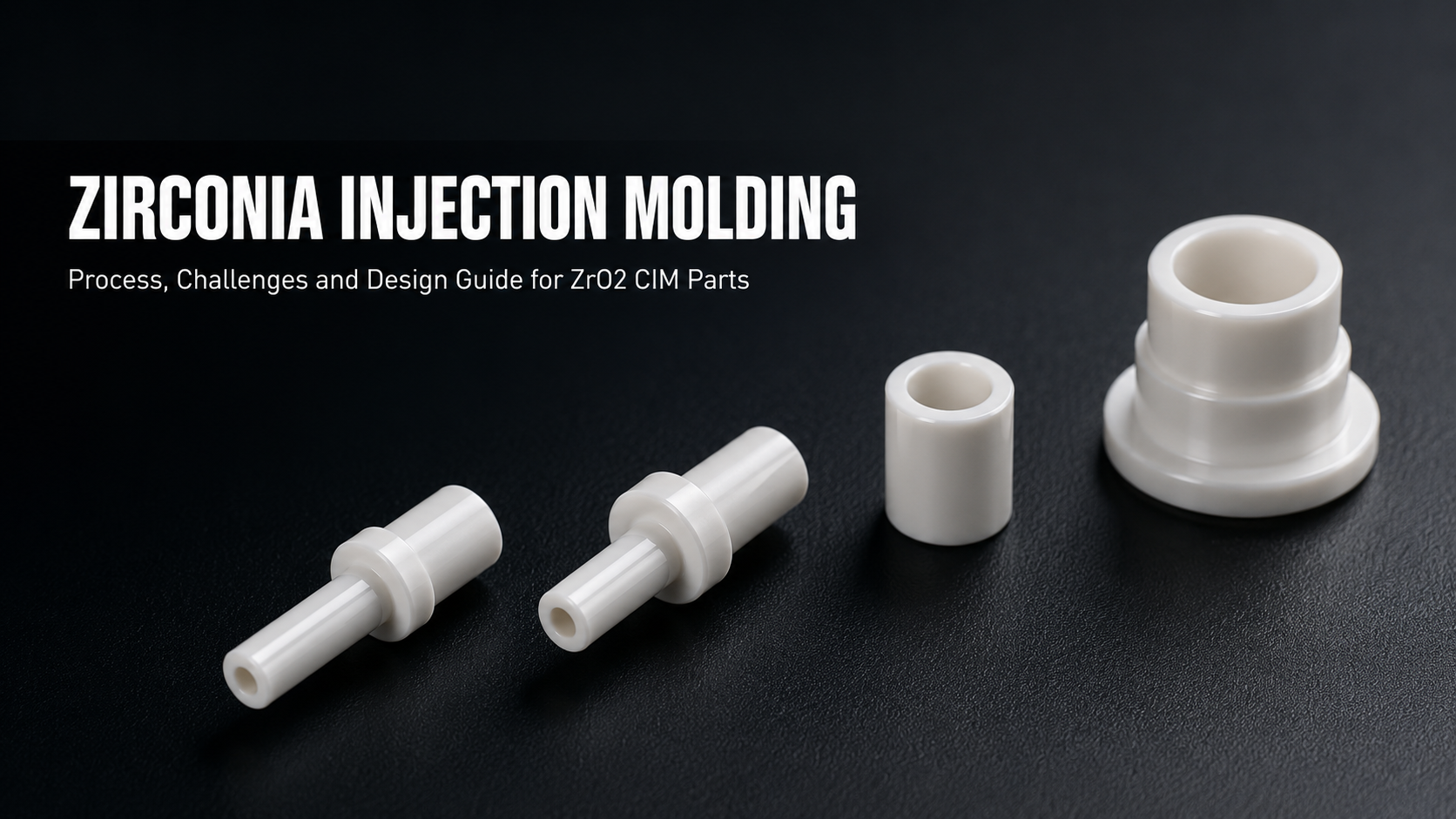
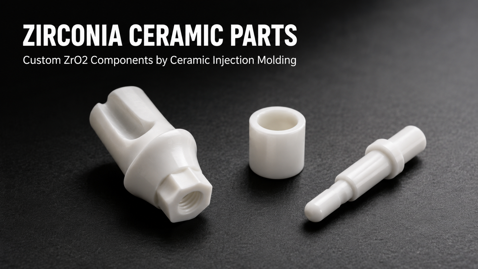
Zirconia ceramic parts are used in some of the most demanding precision applications — dental implant components, fiber optic ferrules, semiconductor handling fixtures, and industrial wear parts. In each of these categories, the majority of complex, high-volume zirconia components are manufactured by Ceramic Injection Molding (CIM), commonly referred to as zirconia injection molding.
CIM allows complex three-dimensional ZrO2 geometries to be produced with near-net-shape accuracy at volumes that make part costs viable for commercial applications. However, zirconia is one of the more technically demanding CIM materials. Phase stability during sintering, shrinkage control, and debinding behavior all require careful process engineering that differs from alumina or other structural ceramics.
This guide covers the complete zirconia injection molding process, the specific technical challenges associated with ZrO2, the design rules that produce reliable parts, and how CIM compares to alternative zirconia manufacturing methods.

Is Zirconia Suitable for Injection Molding?
Yes — zirconia is one of the most commonly CIM-processed advanced ceramics, second only to alumina in global production volume. Its suitability comes from several practical factors:
- Fine ZrO2 powder with median particle size below 0.5 µm is commercially available with consistent purity and particle size distribution
- Zirconia feedstock achieves stable solids loading of 55–62 vol% in standard thermoplastic binder systems
- Sintering in air atmosphere is sufficient for 3Y-TZP — no controlled atmosphere or vacuum is required
- Post-sintering diamond grinding achieves final dimensional tolerances not reachable in the as-sintered state
The primary challenge is that zirconia's final mechanical performance depends critically on sintering cycle control. Unlike alumina, which is relatively forgiving of sintering parameter variation, zirconia's strength and toughness depend on maintaining a specific crystallographic phase — the metastable tetragonal phase — through all processing stages. Departure from this phase results in significantly degraded mechanical properties.
The Zirconia Injection Molding Process Step by Step
Feedstock Preparation
ZrO2 feedstock is prepared by compounding fine yttria-stabilized zirconia powder — typically 3 mol% yttria (3Y-TZP) for structural applications — with a thermoplastic binder system. The binder typically consists of paraffin wax as the primary binder, polyethylene or polypropylene as backbone binder, and stearic acid as a coupling agent and lubricant.
Solids loading — the volumetric proportion of ceramic powder in the feedstock — typically runs at 55–62 vol% for zirconia. Higher solids loading improves dimensional accuracy and reduces debinding time, but increases feedstock viscosity and injection pressure requirements. Consistent solids loading across production batches is essential for batch-to-batch dimensional repeatability.
Feedstock is compounded in a heated twin-screw mixer or sigma-blade mixer, then granulated for use in the injection molding machine.
Injection Molding
Zirconia feedstock is injected into precision steel molds at melt temperatures of approximately 150–185°C and mold temperatures of 40–60°C. Injection pressure varies with part geometry but typically falls in the range of 50–150 MPa.
The result — the green part — contains the full molded geometry at slightly oversized dimensions to account for sintering shrinkage. Green parts are fragile and must be handled carefully. Tooling geometry is designed to account for the 18–22% linear sintering shrinkage that occurs in the subsequent sintering stage.
Debinding
Debinding removes the binder system from the green part, leaving a porous "brown part" that maintains the molded geometry. Two approaches are common for zirconia CIM:
Solvent debinding: The green part is immersed in a solvent — typically heptane or hexane at 40–60°C — which selectively dissolves the primary paraffin wax component. After solvent debinding, approximately 70–80% of the binder is removed. Solvent debinding typically requires 4–24 hours depending on part wall thickness.
Thermal debinding: The solvent-debound brown part is then thermally debound in a furnace with controlled atmosphere (typically air for zirconia) up to approximately 500–600°C. The remaining backbone binder burns out, leaving behind a porous ceramic body with approximately 40–45% porosity. Heating rates during thermal debinding must be controlled carefully — too rapid heating causes binder vapor pressure to build up inside the part, leading to blistering, cracking, or delamination.
Sintering and Phase Stability Control
Sintering is the most technically critical stage in zirconia injection molding. The brown part is loaded into a high-temperature furnace and sintered at approximately 1,350–1,450°C in air atmosphere. During sintering, the ceramic powder grains bond and densify, eliminating porosity and achieving final mechanical properties.
For 3Y-TZP, the sintering cycle must be controlled to achieve two simultaneous goals: full densification (above 99% theoretical density) and preservation of the metastable tetragonal phase at room temperature. Both are influenced by sintering temperature and hold time:
- Too low a sintering temperature or too short a hold time → insufficient density, low strength
- Too high a sintering temperature or too long a hold time → grain growth beyond ~0.5 µm → spontaneous tetragonal-to-monoclinic transformation → reduced strength and toughness, potential surface cracking
Cooling rate from sintering temperature is also controlled. Rapid cooling preserves the metastable tetragonal phase; however, thermal shock risk must be balanced against phase stability requirements. The optimal sintering cycle for each part geometry is developed during process qualification.

Technical Challenges in Zirconia CIM
Phase Transformation and Grain Size Control
The transformation toughening mechanism that gives 3Y-TZP its exceptional fracture toughness depends entirely on the tetragonal phase being present and stable at operating temperatures. Grain growth during sintering is the primary risk factor: above a critical grain size of approximately 0.5–1 µm, tetragonal grains can spontaneously transform to monoclinic, with an accompanying volume expansion of 3–5%. This transformation causes surface cracking in dense parts and destroys the intended mechanical properties.
Preventing abnormal grain growth requires precise control of sintering peak temperature, hold time, and starting powder characteristics. Consistent feedstock powder with controlled particle size distribution and purity is essential.
Low-Temperature Degradation (Hydrothermal Aging)
3Y-TZP is susceptible to a slow tetragonal-to-monoclinic phase transformation at temperatures of 200–300°C in the presence of water vapor — a phenomenon called hydrothermal aging or low-temperature degradation. This is relevant for zirconia parts used in autoclave sterilization (medical/dental), humid industrial environments, or applications involving steam exposure.
For applications where hydrothermal aging is a concern, material grade selection (5Y-TZP offers better aging resistance at some cost to strength), surface quality management, and application-specific testing are discussed during project qualification.
Dimensional Control and Shrinkage Uniformity
Linear sintering shrinkage of 18–22% requires highly precise mold design and consistent feedstock processing. Variation in solids loading, binder distribution, or green density across the part section will produce non-uniform sintering shrinkage and geometric distortion. Parts with highly non-uniform wall thickness are particularly prone to differential shrinkage — a common source of warping or dimensional variation in zirconia CIM.
Defect Types and Prevention
The most common defects in zirconia injection molding are:
- Warping: caused by differential shrinkage from uneven wall thickness or asymmetric mold temperature distribution. Addressed through part design improvements and setter optimization during sintering.
- Surface cracking: caused by too-rapid debinding or thermal shock during sintering. Addressed through controlled debinding schedules and sintering ramp rate optimization.
- Blistering or delamination: caused by trapped binder vapor during thermal debinding. Addressed through extended solvent debinding and reduced debinding heating rates.
- Monoclinic phase contamination: caused by grain growth from excessive sintering temperature or hold time. Addressed through sintering cycle calibration.
Design Rules for Zirconia Injection Molded Parts
Wall Thickness
Recommended wall thickness range is 0.5–15 mm. Walls below 0.5 mm carry elevated risk of warping during sintering and green part breakage during handling. Walls above 15 mm require extended debinding cycles and carry increased risk of internal defects. The optimum range for most precision components is 1–8 mm.
Uniform wall thickness is strongly preferred. Where thick-to-thin transitions are unavoidable, the transition should be gradual — avoid abrupt changes in cross-section. Uniform wall thickness ensures consistent sintering behavior across the entire part.
Holes, Features, and Tolerances
Minimum hole diameter is approximately 0.5 mm. For blind holes, maximum depth-to-diameter ratio is 5:1. Through holes can be deeper. Sharp internal corners concentrate sintering stress and should be replaced with radii of at least R0.2 mm wherever possible.
Draft angles of 0.5–1° are required on injection-molded surfaces for part ejection. Zero-draft sidewalls require additional tooling considerations and add cost.
As-sintered tolerances: ±0.3–0.5% of nominal dimension. For critical features requiring tighter tolerances — bore diameters, seating faces, mating surfaces — diamond grinding after sintering achieves ±0.005 mm or better. Specify grinding allowance in the design at the drawing stage to ensure sufficient material is present on the surfaces to be finished.

Zirconia CIM Compared to Other Zirconia Manufacturing Methods
Engineers new to zirconia often consider multiple manufacturing routes before committing to CIM. The most common comparison points are:
Diamond machining from sintered blanks: Applicable for low volumes and simple geometries. Zirconia sintered blanks are commercially available in rod, plate, and tube form. CNC grinding and machining with diamond tooling produces accurate dimensions but at high cost per part due to slow material removal rates and high tooling wear. For complex geometries, machining is often 5–20× more expensive per part than CIM at equivalent volumes.
Dry pressing or cold isostatic pressing (CIP): Suitable for axisymmetric or block geometries. Produces parts at very low cost but is limited to geometries achievable by pressing — no internal features, undercuts, or complex external profiles. CIM offers far greater geometric freedom.
Slip casting: Used for large or thin-walled zirconia shapes. Slower cycle times and less precise dimensional control than CIM. More appropriate for ceramic art, large industrial tubes, and crucibles than precision engineering components.
For precision components with complex geometry at production volumes above approximately 500–1,000 pieces per year, CIM is almost always the most cost-effective route. Below this volume, machining from sintered blanks or pressed and machined blanks may be more practical, depending on geometry.
Quality Control for Zirconia Injection Molded Parts
Zirconia CIM parts are subject to multiple quality checkpoints through the manufacturing process:
- Feedstock quality: solids loading verification by thermogravimetric analysis (TGA); melt flow index measurement for injection consistency
- Green part inspection: dimensional check of green part dimensions; visual inspection for surface defects, incomplete fill, flash
- Sintered density: Archimedes method density measurement; target >99% of theoretical density (6.08 g/cm³ for 3Y-TZP)
- Phase analysis: X-ray diffraction (XRD) to confirm tetragonal phase content; monoclinic phase fraction should be <5% for structural parts
- Dimensional inspection: CMM measurement of all critical dimensions; surface roughness measurement on functional surfaces
- Mechanical testing: Vickers hardness; flexural strength by 3-point or 4-point bend testing on batch witness samples
- Visual and dye penetrant testing: surface crack detection on critical parts
The specific inspection plan for each project is agreed with the customer during the first article inspection (FAI) stage before production release.

Application Case: Zirconia Injection Molded Ferrule for Fiber Optic Connector
The fiber optic connector industry represents one of the highest-volume global applications for zirconia CIM. The standard single-mode fiber optic ferrule — used in SC, LC, FC, and ST connectors — is a zirconia ceramic tube with an outer diameter of 1.25 or 2.5 mm, a 125 µm bore diameter, and a total length of 10–25 mm. The bore concentricity requirement is typically less than 1 µm.
Producing ferrules by machining from sintered ZrO2 rod is not practically feasible at connector manufacturing volumes. CIM produces the near-net-shape ferrule, after which the bore and outer diameter are brought to final dimensions by precision cylindrical grinding and lapping to achieve bore concentricity within specification.
A typical ferrule production program involves 3Y-TZP CIM, solvent and thermal debinding, sintering at 1,380°C, and multi-stage precision cylindrical grinding. Bore lapping achieves surface roughness of Ra < 0.05 µm on the end face. Production batches run at tens of thousands of pieces per month with statistical process control applied to concentricity, outer diameter, and length.
This application demonstrates the scalability and precision achievable with zirconia injection molding for high-tolerance ceramic components where no alternative manufacturing method is practically viable.
What to Provide for a Zirconia Injection Molding Quotation
- 2D engineering drawing with all critical dimensions, tolerances, and surface finish specifications
- 3D model in STEP, STP, X_T, or IGES format
- Material grade specification — 3Y-TZP for structural, 5Y-TZP for dental/translucent applications, or other if specified
- Annual production volume and initial prototype or sample quantity
- Application description and operating environment
- Relevant standards or certifications — ISO 13356 for medical, specific semiconductor equipment standards if applicable
- Secondary finishing requirements — grinding dimensions and tolerances, surface roughness targets, lapping requirements
If geometry complexity or tolerance requirements are uncertain, send us the drawing for a DFM (Design for Manufacturability) review before finalizing the part design. Identifying features that would drive unnecessary cost or manufacturing risk at the design stage avoids expensive tooling revisions later.
FAQ
What is zirconia injection molding?
Zirconia injection molding, formally called Ceramic Injection Molding (CIM), is a manufacturing process that produces complex ZrO2 ceramic components by injecting a mixture of fine zirconia powder and thermoplastic binder into a precision mold, then removing the binder and sintering the ceramic to full density. It is the standard manufacturing method for high-volume, complex-geometry zirconia parts.
What grades of zirconia are used in CIM?
3 mol% yttria-stabilized tetragonal zirconia polycrystal (3Y-TZP) is the most common grade for structural and industrial zirconia CIM parts. 5Y-TZP is used where increased translucency or improved hydrothermal aging resistance is required, particularly in dental applications. The grade selection depends on the mechanical, optical, and environmental requirements of the application.
What tolerances are achievable with zirconia CIM?
As-sintered zirconia CIM parts achieve ±0.3–0.5% of nominal dimension. Secondary diamond grinding achieves ±0.005 mm or better on critical surfaces. Precision lapping of bore or flat surfaces achieves surface roughness below Ra 0.05 µm. The achievable tolerance depends on part geometry, feature size, and the extent of secondary finishing specified.
How does zirconia CIM compare to alumina CIM in process difficulty?
Zirconia CIM is technically more demanding than alumina CIM. Alumina is relatively tolerant of sintering temperature variation and does not have phase stability concerns. Zirconia requires tighter sintering temperature and hold time control to prevent monoclinic phase formation and grain growth. Feedstock quality and solids loading consistency are also more critical for zirconia. These factors make zirconia CIM process qualification more involved, but the process is well-established for production volumes in many application categories.
What is the minimum wall thickness for zirconia injection molded parts?
The recommended minimum wall thickness is 0.5 mm, with 0.8 mm preferred for reliable production. Walls below 0.5 mm carry elevated risk of warping during sintering and handling damage. For very thin features, alternative geometry arrangements or post-sintering grinding to final thickness may be the better approach.
Zirconia injection molding is a well-developed process capable of producing precision ZrO2 components at production volumes across medical, dental, semiconductor, fiber optic, and industrial applications. Process complexity is higher than for alumina, but for applications that require zirconia's unique combination of strength, toughness, and biocompatibility, CIM is the most efficient manufacturing route available. Contact us with your drawing for a DFM review and project evaluation.

Share:
Sintered Tungsten Carbide: Process, Properties, and Custom Part Applications
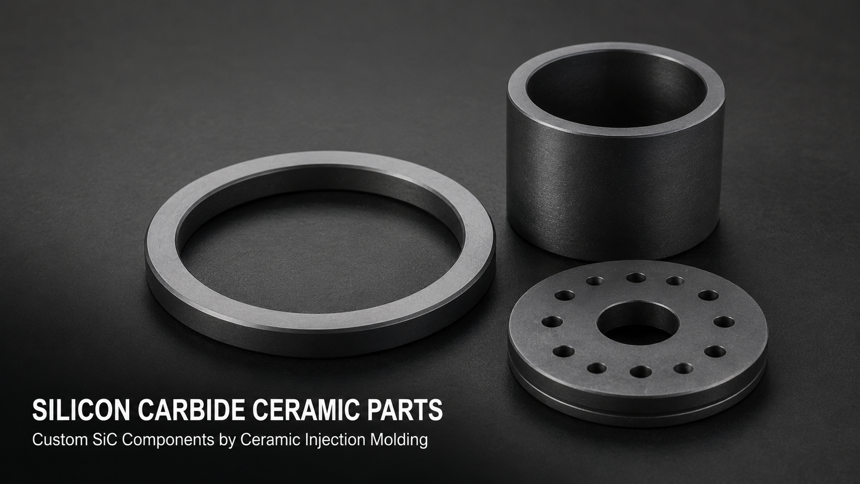
Silicon Carbide Ceramic Parts: Custom SiC Components by Ceramic Injection Molding