

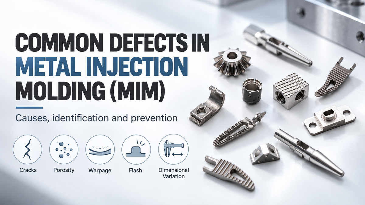
Metal injection molding (MIM) is a good fit for small, complex metal parts that would otherwise require several machining or assembly steps. It can produce detailed geometries, thin walls, internal features, and high volumes with good repeatability.
Still, the process has its own challenges.
Unlike conventional plastic injection molding, a metal injection molded part is not finished when it leaves the mold. MIM defects requires looking at the whole process, not just the stage where the problem becomes visible. In this article, we will look at the most common metal injection molding defects, what causes them, and how to prevent them. We will also share how XY-GLOBAL applies hands-on manufacturing experience and process control to produce MIM parts with consistent quality and reliable performance.
For a quick overview, you can read the table below first:
| MIM Defect | Typical Stage | Common Causes |
| Warpage | Debinding / Sintering | Uneven wall thickness, density variation, poor support |
| Cracking | Molding / Debinding / Sintering | Internal stress, fast debinding, weak weld lines |
| Short shot | Injection molding | Poor flow, low temperature, insufficient venting |
| Flash | Injection molding | Excess pressure, mold wear, poor shutoff |
| Weld lines | Injection molding | Flow fronts meeting in critical areas |
| Blistering | Debinding | Binder removal too fast |
| Porosity | Sintering | Poor feedstock uniformity, insufficient densification |
| Uneven shrinkage | Sintering | Density variation, geometry, furnace conditions |
| Dimensional variation | Entire process | Tooling, shrinkage, support, process variation |
| Discoloration | Sintering / Finishing | Atmosphere, contamination, residual binder |
Why Defects Form in Metal Injection Molding
The MIM process combines injection molding with powder metallurgy. That combination creates opportunities that conventional machining cannot easily match, but it also means more process variables need to stay under control.
The feedstock contains fine metal powder mixed with a binder system. During injection, the material has to fill the cavity evenly. After molding, enough binder must be removed without damaging the shape. The remaining structure then goes through sintering, where the powder particles bond together and the part approaches its final density.
Typical linear shrinkage during sintering is often around 15–20%, although the actual value depends on the alloy, feedstock, powder loading, and sintering process.
That shrinkage is expected. The real problem is when different areas of the same part shrink differently.
Think of a part with a thin wall on one side and a heavy boss on the other. Both areas may look fine after molding, but they do not cool, debind, or densify in exactly the same way. That difference can later show up as warpage or dimensional movement.
For this reason, good MIM production starts with design and material control long before the sintering furnace is involved.

Warpage and Distortion
Warpage is one of the most common problems in metal injection molding, especially on long, thin, flat, or asymmetric parts.
The basic cause is uneven movement during the process.
Different sections of the part may contain slightly different residual stresses or local powder concentrations. Some areas are better supported than others during sintering. Gravity can also affect the part while the metal structure is densifying.
A green part may look completely straight and still distort later.
Wall thickness has a big influence here. Sudden changes between thin and thick sections create different thermal and shrinkage behavior. Large flat areas and unsupported arms are also more difficult to control.
In practice, the best time to reduce warpage risk is during DFM.
More uniform wall thickness usually helps. Heavy sections can sometimes be cored out instead of left solid. Ribs may provide stiffness without adding too much mass.
Gate location matters too. If the cavity fills unevenly, the molded part may already contain stress before debinding begins.
For parts that are naturally difficult to support, custom ceramic sintering fixtures can be used. The fixture needs to support the part without stopping normal shrinkage. A fixture that holds the component too tightly can create a different dimensional problem.
The goal is not to force the part into position. It is to guide the shrinkage in a predictable way.
Cracking
Cracks can appear during molding, debinding, or sintering, and the timing gives useful clues about the root cause.
A green-part crack may come from ejection stress, a weak weld line, poor filling, or rough handling. Cracks that appear during debinding are more often connected to binder removal. Sintering cracks may point to density differences, remaining binder, contamination, or stress already present in the part.
Debinding needs particular care because the part is gradually losing the binder that gives it strength.
The binder or its decomposition products must escape from inside the component. If this happens too quickly, internal pressure can build up. Thick areas are usually more sensitive because gases have a longer path to travel.
That is why very heavy solid sections can be problematic in metal injection molding.
A design that works well in CNC machining may not automatically be ideal for MIM. If a thick section is not functionally necessary, it may be better to redesign it with ribs, pockets, or a hollow structure.
The debinding cycle also needs to match the binder system and geometry. Heating too aggressively may save time on paper but increase cracking risk. A stable process is usually more valuable than the shortest possible cycle.
Short Shots and Incomplete Filling
A short shot happens when the feedstock does not completely fill the mold cavity.
The result may be obvious, such as a missing corner, or more subtle. A narrow rib may be incomplete. A small hole feature may not form correctly. A thin section may have a rounded edge instead of the intended geometry.
MIM feedstock contains a high concentration of metal powder, so its flow behavior is different from ordinary plastic resin.
Poor filling can come from low material temperature, insufficient mold temperature, incorrect injection speed, restricted gates, long flow paths, or trapped air.
Sure, injection pressure can sometimes be increased. But simply pushing harder is not always the right fix.
The better approach is usually to review the complete flow path.
A gate may be too small. A thin section may be located too far from the gate. Venting may be weak at the end of fill. The flow direction may also be working against the geometry.
For thin-wall or micro MIM parts, relatively small changes in gate design and mold venting can make a noticeable difference.
Flash
Flash is the thin excess material that appears around parting lines, ejector areas, slides, or other mold interfaces.
In most cases, the causes are familiar: excessive pressure, poor mold fitting, insufficient clamping, or wear on shutoff surfaces.
The difference with MIM is that flash becomes metal after sintering.
A soft piece of green-part flash may be easy to remove before sintering. Once the component is fully densified, the same feature becomes harder and more expensive to clean up.
This makes mold maintenance important, especially on high-volume programs.
A tool that performs well during early production can still develop flash later as shutoffs wear. Monitoring the mold condition is therefore part of maintaining consistent part quality.
Weld Lines and Flow Marks
Weld lines appear where two material flow fronts meet inside the cavity.
They are not always serious. On a low-stress cosmetic surface, a weld line may have little impact. But when it forms near a thin feature, hole, snap, or load-bearing area, it deserves more attention.
In metal injection molding, a weak weld region can remain a structural weakness through the later process stages.
Poor bonding at the flow front may contribute to cracking or reduced mechanical strength after sintering.
Gate placement has a strong effect on where weld lines form. During mold design, it is often possible to move them away from critical areas by changing the gate location or fill direction.
Flow marks and jetting are related problems.
Jetting occurs when the feedstock shoots into the cavity as a narrow stream instead of flowing smoothly along the mold surface. That stream can fold back on itself and leave visible patterns or local material variation.
Changes to the gate, injection speed, or flow direction can usually improve the situation.
Sink Marks and Uneven Packing
Sink marks usually appear near thicker sections where the material cools and contracts differently from the surrounding area.
A common example is a thick boss attached directly to a much thinner wall.
Adjusting packing pressure may help, but it cannot always compensate for poor geometry.
At some point, the design itself becomes the limiting factor.
This is why uniform wall thickness is more than a general design recommendation. It affects filling, cooling, binder removal, and later shrinkage.
In some cases, replacing a heavy solid boss with a cored structure can reduce sink risk while also making debinding and sintering more predictable.
Blistering and Incomplete Debinding
Blistering often shows up as raised bubbles or swollen areas on the part surface.
The problem usually begins when binder or decomposition gases cannot leave the part fast enough during debinding.
The outside of the component may already be more porous while the center still contains a higher amount of binder. If the internal material starts to decompose faster than it can escape, pressure builds under the surface.
The result may be blistering, cracking, or hidden internal damage.
Incomplete debinding causes a different but related problem.
If too much binder remains before sintering, it can affect surface condition, carbon level, porosity, and final material properties. In some alloys, small chemistry changes can have a noticeable impact on performance.
The correct cycle depends on the binder system.
Metal injection molding manufacturers may use solvent debinding, catalytic debinding, thermal debinding, or a combination of methods. No single method is automatically best for every application.
What matters is that the binder is removed in a controlled way without damaging the part.
Porosity and Low Density
Some level of microscopic porosity is normal in many MIM materials, but excessive or uneven porosity can become a real quality issue.
Porosity can reduce mechanical strength. It may also affect sealing, polishing, plating, fatigue life, or corrosion behavior depending on the application.
The root cause may begin with the feedstock.
If powder and binder are not distributed uniformly, local areas can contain different powder concentrations. Those areas may then densify differently during sintering.
Sintering conditions also matter. Temperature, time, furnace atmosphere, and loading all influence densification.
In real production, consistency matters more than chasing one impressive density number.
A process that repeatedly delivers a stable density range is more useful than one batch that reaches a very high value while later batches vary.
Density measurement gives useful information, but it does not always show the full picture. Metallographic inspection can reveal pore size and distribution. For critical components, mechanical testing or CT inspection may also be used when necessary.
Uneven Shrinkage and Dimensional Variation
Shrinkage itself is part of metal injection molding. Uneven shrinkage is where problems begin.
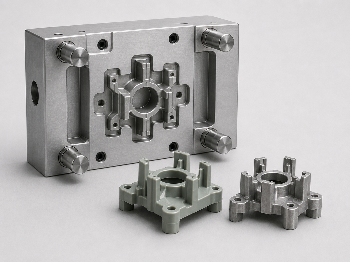
The mold cavity is intentionally made larger than the final component because the part will shrink during sintering. The tooling compensation is based on the specific material system and process.
On paper, this sounds simple.
In practice, the shrinkage is affected by powder loading, part geometry, fill pattern, sintering support, and furnace conditions.
A long dimension may behave differently from a small diameter. A heavy feature can move differently from a thin wall. Flatness and straightness across a long section are usually more difficult to control than a compact molded dimension.
This is why applying one shrinkage factor to every feature without considering geometry can lead to trouble.
Experienced MIM suppliers rely on process history, tool correction data, and actual sample measurements to refine final dimensions.
The same logic applies to tolerance.
Metal injection molding can achieve good dimensional repeatability, but not every feature should automatically receive the same tight tolerance.
A ±0.01 mm requirement may be realistic on one small, well-supported feature but unnecessary or difficult on a long sintered profile.
Critical dimensions should be identified early.
Where MIM alone cannot reliably hold the final requirement, secondary machining, grinding, sizing, or another finishing process may be more practical than forcing the entire molding process into a narrow window.
Surface Discoloration and Contamination
Discoloration after sintering can come from oxidation, furnace atmosphere, residual binder, contamination, or contact with support materials.
Sometimes the issue is only cosmetic. In other cases, the color change may point to something that needs closer investigation.
Atmosphere control is particularly important for stainless steels and other alloys that are sensitive to surface chemistry.
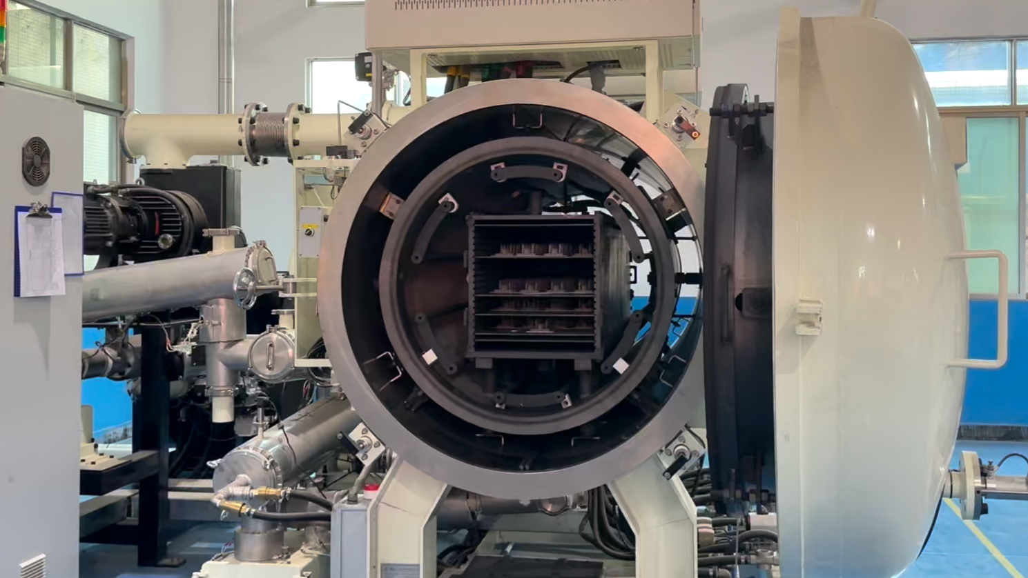
Vacuum, hydrogen, inert gas, or other furnace conditions may be used depending on the material and desired properties.
Contamination can also enter the process earlier.
MIM uses fine metal powders, so material handling needs reasonable control. Residue from another alloy, dirty tooling, or poor equipment cleaning can affect local chemistry.
This becomes more important for medical, automotive, electronic, or other applications where material consistency and traceability matter.
Practical Troubleshooting for Common MIM Defects
Not every defect requires a new mold. That is worth keeping in mind because tooling changes are expensive and usually take more time than process adjustments.
The first step is to identify where the defect is most likely being created.
| Defect | First Areas to Check | Typical Corrective Direction |
| Warpage | Wall thickness, filling balance, sintering support | Improve geometry, process balance, or fixture |
| Cracking | Weld lines, ejection, debinding cycle | Reduce stress and slow binder removal where needed |
| Short shot | Gate, venting, temperature, injection speed | Improve flow and cavity filling |
| Flash | Pressure, clamp force, shutoff surfaces | Optimize molding or repair mold |
| Weld line | Gate position and flow pattern | Relocate flow meeting point |
| Blistering | Debinding temperature and part thickness | Adjust binder removal rate |
| Porosity | Feedstock, furnace profile, atmosphere | Improve material and sintering control |
| Dimensional variation | Shrinkage data, support, tool compensation | Refine process or tooling compensation |
| Discoloration | Furnace atmosphere and contamination | Check furnace and material handling |
The key is to change one thing for a reason.
Changing several molding and sintering parameters at the same time may produce a better sample, but it also makes the process harder to understand. Once something changes again later, the original solution may be difficult to reproduce.
Preventing MIM Defects Before Tooling Starts
Many metal injection molding problems are easier to prevent in DFM than to correct after tooling.
A drawing may look perfectly reasonable from a functional point of view but still create unnecessary manufacturing risk.
Large wall-thickness changes are a good example. Long unsupported sections are another. Critical dimensions placed across a difficult parting line may also make the mold and inspection process more complicated than necessary.
A proper MIM DFM review should look at how the cavity fills, where the gate can be placed, how the part will be ejected, and how it will behave during debinding and sintering.
Tolerance needs to be considered at the same time.
There is little value in assigning very tight tolerances to every dimension if only two or three features actually affect assembly or function.
It is often better to identify the truly critical dimensions and build the process around those.
That approach gives engineering and production teams more room to control the part consistently.
Feedstock and Process Consistency Matter
Tooling gets a lot of attention in MIM, but the material side is just as important.
A stable feedstock needs a consistent relationship between powder and binder.
If the material begins to separate, local powder loading can change. The green part may still look normal, yet shrinkage or density problems may appear after sintering.
Storage, handling, drying when required, and regrind control can all affect consistency.
The molding process also needs a stable window.
Pressure, temperature, speed, and cycle conditions do not need to be identical for every MIM material. What matters is that the selected range works reliably for that particular feedstock and geometry.
This is one reason historical production data is useful. Once a process is proven, future production should stay close to the validated conditions instead of being adjusted casually from batch to batch.
Inspection Should Match the Part Risk
Not every MIM feature needs the same inspection method.
Simple dimensions may be checked with standard measuring equipment. Complex profiles or tight positional relationships may require a CMM or vision system. Surface quality, density, hardness, or material structure may need separate testing depending on the project.
The inspection plan should follow function.
Critical assembly dimensions deserve more attention than non-functional cosmetic features. Parts used in medical devices or other controlled applications may also require lot traceability and additional documentation.
Here’s the thing: inspection does not create quality. It confirms whether the process is producing the expected result.
The stronger the manufacturing process is, the less inspection becomes a search for unexpected problems.
First Samples Do Not Need to Be Perfect
Finding a defect during the first molding trial does not automatically mean the MIM process is failing.
That is what early trials are for.
The first samples show how the real material, mold, and part geometry behave together. A slight dimensional offset may need tool compensation. A flat part may require a different sintering support. A thin rib may need a gate adjustment.
What matters is whether the cause can be understood and controlled.
A supplier that can explain the problem, test a correction, and establish a repeatable process is in a much stronger position than one that simply keeps changing parameters until a sample happens to pass.
How XY-GLOBAL Supports Stable Metal Injection Molding Production
At XY-GLOBAL, defect prevention starts before the production mold is finalized.
Our engineering team reviews the part geometry, material, expected volume, critical dimensions, gate strategy, and possible sintering risks during the early project stage. When needed, we also consider sintering fixtures, secondary machining, and inspection requirements before production begins.
Sample development is then used to confirm how the actual part behaves.
Dimensions, shrinkage, appearance, and other required characteristics are checked before moving into stable production. If adjustments are needed, they can be made based on the actual manufacturing result rather than assumptions.
The purpose is not to produce one good sample under special conditions. The process needs to remain stable when production quantities increase.
If you are developing a part for metal injection molding, you can send us the 2D/3D drawings, material requirement, expected annual quantity, and critical dimensions. Our team can review the design and identify potential MIM manufacturing risks before tooling starts.
Final Thoughts
Metal injection molding can produce complex metal components efficiently, but it is not a process where tooling alone determines the result.
Part geometry, feedstock, molding, debinding, sintering, and inspection all influence final quality.
Most defects become easier to solve once the process is viewed as one connected system.
Warpage is not always a furnace problem, and dimensional variation may come from uneven material distribution rather than poor inspection.
Understanding where a defect begins is what allows the process to be corrected and, more importantly, kept stable when production scales up.
Compartir:
Fabricantes de aisladores cerámicos personalizados para aplicaciones industriales
Sizing Process in Powder Metallurgy: Purpose, Steps, and Tolerances